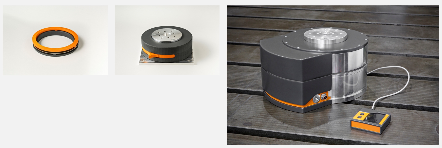
Faster Development & Testing enabled by Hybrid Test Solutions

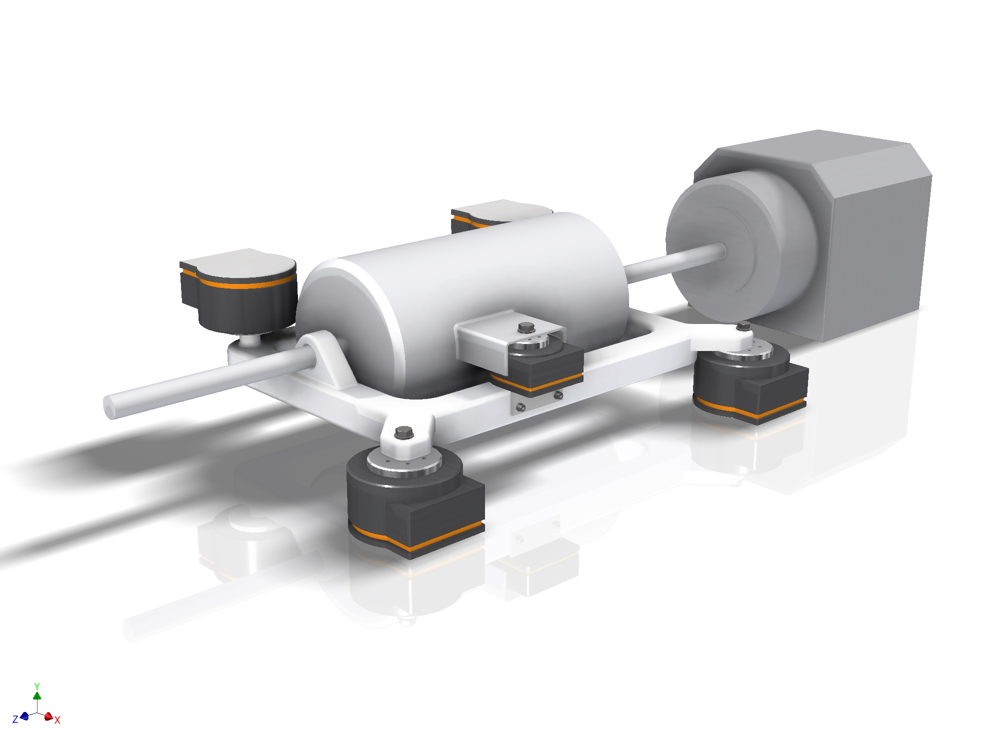
HyTest offers hardware solutions and technology to adjust, adapt and emulate mechanical characteristics. We have developed these solutions to let R&D and test engineers get their jobs done faster and more efficient. Examples for these solutions are mounts with stiffness tuning, vibration absorbers with tunable frequency and damping as well as energy efficient mechanical Hardware-in-the-loop solutions. 

Currently we are looking for partners to bring the solutions to the market. If you want to become an early adopter* of these game-changing solutions, please contact us!

* As user or as licensee.

What is hybrid testing?

During product development of complex systems a variety of methods are applied. Numerical methods are very beneficial when it comes to analyze different scenarios in a very short time and in an early stage of the development process. The variation of parameters and characteristics is easy and can be automated. 

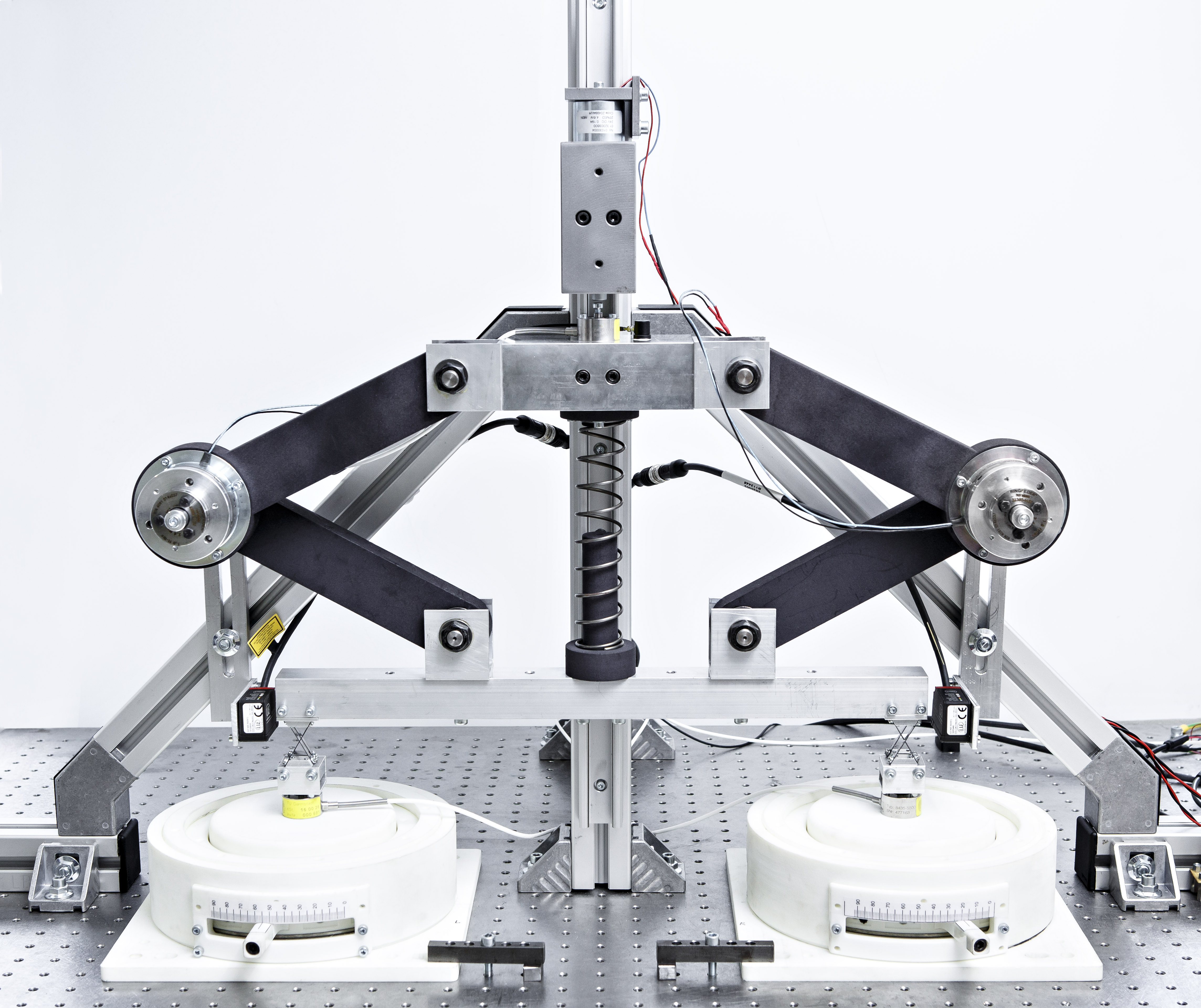
Experiments in laboratories, testing facilities and on test tracks are nevertheless necessary and are widely applied. If a scenario or a system is too complex to build a sufficient numerical model physical experiments are carried out. Complex test rigs are used for Noise Vibration Harshness (NVH) development, reliability testing or the validation of numerical models. When it comes to the variation of parameters or mechanical characteristics there is often a high effort in physical experiments. Numerous prototype parts are necessary and they have to be exchanged several times in the test rig to vary a single mechanical parameter.

Hybrid testing combines the advantages of numerical and experimental methods. There are two approaches:

  1. Coupling test rigs with numerical real-time simulations. Often this approach is also called Hardware-in-the-loop testing. A device under test is coupled with a numerical real-time simulation of the rest of the system using a suitable interface.
  2. Bringing the advantages of the numerical simulation to physical experiments and test rigs. We have developed solutions, which allow rapid variation of mechanical parameters in physical experiments. 

Our HyTest Solutions safe time, money and reduce the time to market of products.


Rapid parameter variation based on stiffness tuning

Stiffness tuning mechanism by Fraunhofer LBF
© Raapke/ Fraunhofer LBF

Our solutions are based on a unique stiffness tuning mechanism. The solution is based on a spring element, made of sheet metal or plastics. The spring element has a ring-like shape. Three connecting points on each side connect it to the surrounding structures. The stiffness is defined by the angle between the Connecting points of Structure 1, relative to Structure 2. The solution is scalable in a wide range regarding:

  • The stiffness tuning range. Allowing continuous stiffness tuning up to factor 150 between the low- and high-stiffness settings.
  • The payload. Reaching from very low to very high loads. Literally from grams to tons.
Tunable Mount by Fraunhofer LBF
© Raapke / Fraunhofer LBF
Tunable Mount, 300 N/mm to 10 kN/mm
Stiffness tuning mechanism by Fraunhofer LBF
© Fraunhofer LBF
Stiffness tuning mechanism
force - stroke characteristics, measurement results
Measured force-stroke characteristics for different settings

Applications in Research & Development

Concept for drivetrain testrig based on HyTest Solutions
© Fraunhofer LBF
Concept for drivetrain testrig based on HyTest Solutions
Tunable vibration absorber prototype. 30 Hz - 120 Hz
© Fraunhofer LBF
Tunable vibration absorber prototype. 30 Hz - 120 Hz
Mechanical Hardware-in-the-loop interface emulating the top mount and car body in a test rig for shock absorbers.
© Raapke / Fraunhofer LBF
Mechanical Hardware-in-the-loop interface emulating the top mount and car body in a test rig for shock absorbers.

There are two main application fields for our HyTest Solutions. The flexible emulation of boundary conditions for component testing and the ability of rapid variation of mechanical parameters.

As an example serves the development of an electric drivetrain and a hydraulic shock absorber as devices under test (DUT). Beside several other requirements, the NVH (Noise Vibration Harshness) behavior is crucial for the comfort of vehicles. Besides external excitations, the chosen components (subframe, rubber mounts, vibration absorbers) as well as the dynamic interactions between the drivetrain, shock absorber and car body have a relevant impact on the NVH behavior.

Parameter variation

For the final specification of rubber mounts or vibration absorbers experiments are carried out, typically in a test vehicle or in a test rig. Based on initial numerical simulation the supplier produces prototypes with slightly differing characteristics (stiffness, damping, tuning frequency). For each prototype, tests are carried out to identify the characteristics for the best system performance. Between the tests the different prototypes have to be exchanged by mechanics or test engineers.

Using our tunable mount or our tunable vibration absorber as a development tool, this process massively speeds up. Instead of waiting for the prototypes from the supplier, you can set the tunable mount or vibration absorber to the desired characteristic and run the test. After that, you just change the setting and run the next test. This process can even be automated.  

Boundary conditions

In the car, the drivetrain has a strong dynamic interaction with the car body. At the moment there are several ways to deal with these interactions in test rigs. Typical ways are to work with passive replacement structures or the actual body in white as boundary conditions for DUT in the test rig. This leads to high efforts for the design of the replacement structure. When the actual body in white should be used, it has to be available, so these tests cannot be done early in the development process. These solutions are static, so if the boundary conditions should be changed, parts have to be exchanged.

Using our tunable mounts as boundary conditions allows the rapid variation of the stiffness at the connecting points. Going one step further it is possible to use a mechanical Hardware-in-the-loop approach to emulate the actual dynamics of the car body in the test rig. Therefore, no physical body in white is needed as boundary condition; you just need the numerical model of the car body. This allows carrying out the first tests under realistic boundary conditions way earlier in the development process.    


Mechanical Hardware-in-the-loop

In Hardware-in-the-loop tests the device under test (DUT) is coupled with a numerical real-time simulation of the rest of the system (ROTS) using a suitable interface. The method is well known and widely used for testing of electronic control units. The DUT and the ROTS are exchanging signals on a low power level. For this reason, it is called signal-level Hardware-in-the-loop (sHIL). When the interface between the DUT and the ROTS handles high amount of electrical power the method is called power-level Hardware-in-the-loop (pHIL). Tests of electrical drives or batteries are typical applications.

Our research focus is on mechanical-level Hardware-in-the-loop (mHIL). Here we developed an innovative, energy efficient mechanical Hardware-in-the-loop interface. It is based on our stiffness tuning technology, which allows handling high loads and emulating high stiffnesses. 

Different Hardware-in-the-loop approaches with interfaces on signal-, mechanical- and power-level
© Fraunhofer LBF
Different Hardware-in-the-loop approaches with interfaces on signal-, mechanical- and power-level
Mechanical Hardware-in-the-loop Interface (prototype) by Fraunhofer LBF
© Raapke / Fraunhofer LBF
Mechanical Hardware-in-the-loop Interface (prototype)
Emulation of a resonant structure using a mHIL approach
© Fraunhofer LBF
Emulation of a resonant structure using a mHIL approach

Contact

Do you have questions?

Are you interested in becoming a user of our solutions?

Are you interested in licensing our solutions?

Contact us!